


When evaluating steel pipes for low-pressure gas, water supply, or fire sprinkler networks, the EN 10255 standard is a universal reference on almost every technical inquiry. For procurement professionals, it is common practice to compare quotations based primarily on the per-ton price. However, in practical construction and installation, an unexpectedly low initial price can lead to significant hidden costs.
If the pipes delivered to the project site cause issues like premature tool wear during threading, minor joint leaks, or early corrosion at the connection threads, the initial cost savings are quickly offset by labor delays and rework expenses. As an experienced manufacturing team handling the entire process from raw steel processing to final testing, we believe that understanding a few key production details can help ensure your project stays securely within budget.
Why Smooth Threading Requires Strict Carbon Content Control
The formal title of the EN 10255 specification highlights that these tubes are specifically designed for “welding and threading.” Despite this clear definition, many buyers report frustrating experiences during site installation, such as severe vibration in automated threading machines, rough or torn thread profiles, and frequent chipping of expensive cutting dies.
The underlying cause typically traces back to excessive material hardness and unstable chemical composition.
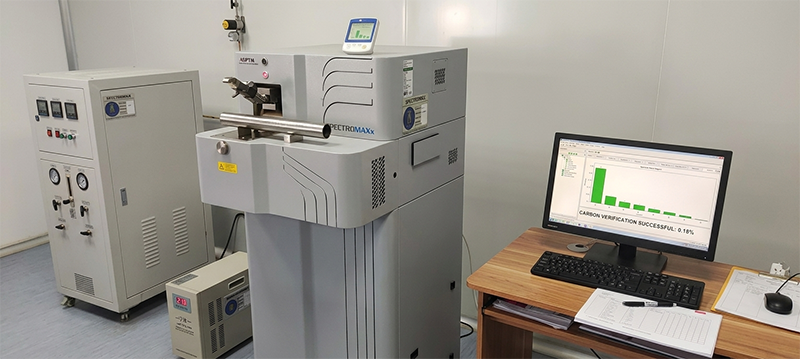
To reduce production costs, some manufacturers may utilize generic steel coils with highly inconsistent chemical properties. For genuine S195T grade tubes, the chemical composition must be managed tightly right from the raw material stage:
Carbon (C): Maintained strictly below 0.20%
Manganese (Mn): Controlled under 1.40%
Phosphorus (P) & Sulphur (S): Maximum limits set at 0.035% / 0.030%
By keeping the carbon content firmly under the 0.20% threshold, the steel retains its proper ductility. When the on-site cutting tools engage the pipe, the material machines smoothly and evenly. This approach protects your threading equipment from premature damage and ensures clean, deep threads that mate perfectly with standard couplings to form a completely reliable, leak-free joint.
The Absolute OD Limits Table
When searching for EN 10255 specifications online, many available summaries present a simplified overview featuring a single outside diameter value—such as 48.8 mm for a DN40 pipe. For a project engineer or quality supervisor, relying solely on a single nominal number is insufficient.
EN 10255 does not operate on a vague percentage-based tolerance like “±1%.” Because these tubes must interface seamlessly with standardized threaded or grooved fittings, the standard defines an absolute maximum and minimum millimeter range for every size.
If the pipe diameter exceeds the upper limit by even 0.1 mm, the threading die may fail to engage correctly. Conversely, if the diameter is too narrow, the resulting thread depth will be insufficient, which frequently triggers failures during hydrostatic testing. Below are the precise boundaries maintained during our workshop mill calibrations:
| Size (DN) | Thread Size (Inch) | Light OD Range (mm) | Medium/Heavy OD Range (mm) | Light Wall (mm) | Medium Wall (mm) | Heavy Wall (mm) | Medium Weight (kg/m) |
| DN8 | 1/4″ | 13.2 – 13.6 | 13.2 – 13.9 | 1.8 | 2.3 | 2.9 | 0.641 |
| DN10 | 3/8″ | 16.7 – 17.1 | 16.7 – 17.4 | 1.8 | 2.3 | 2.9 | 0.839 |
| DN15 | 1/2″ | 21.0 – 21.4 | 21.0 – 21.7 | 2.0 | 2.6 | 3.2 | 1.210 |
| DN20 | 3/4″ | 26.4 – 26.9 | 26.4 – 27.2 | 2.3 | 2.6 | 3.2 | 1.560 |
| DN25 | 1″ | 33.2 – 33.8 | 33.2 – 34.2 | 2.6 | 3.2 | 4.0 | 2.410 |
| DN32 | 1-1/4″ | 41.9 – 42.5 | 41.9 – 42.9 | 2.6 | 3.2 | 4.0 | 3.100 |
| DN40 | 1-1/2″ | 47.8 – 48.4 | 47.9 – 48.8 | 2.9 | 3.2 | 4.0 | 3.570 |
| DN50 | 2″ | 59.6 – 60.2 | 59.7 – 60.8 | 2.9 | 3.6 | 4.5 | 5.030 |
| DN65 | 2-1/2″ | 75.2 – 76.0 | 75.3 – 76.6 | 3.2 | 3.6 | 4.5 | 6.430 |
| DN80 | 3″ | 87.9 – 88.7 | 88.0 – 89.5 | 3.2 | 4.0 | 5.0 | 8.370 |
| DN100 | 4″ | 113.0 – 113.9 | 113.1 – 114.9 | 3.6 | 4.5 | 5.4 | 12.200 |
| DN125 | 5″ | — | 138.5 – 140.6 | — | 5.0 | 5.4 | 16.600 |
| DN150 | 6″ | — | 163.9 – 165.1 | — | 5.0 | 5.4 | 19.700 |
(Note: Under official EN 10255 guidelines, larger dimensions such as 5″ and 6″ do not include a Light series option, which is represented by the “—” in the chart.)
Quality Protocol: Ensuring Accurate Thickness Verification
Some promotional literature suggests that wall thickness inspections are routinely performed deep within the center of a finished tube during high-speed manufacturing. From a practical standpoint, executing a mid-tube micrometer check on every high-speed production run is structurally unfeasible. Our quality verification process focuses on a transparent, practical, and highly accurate methodology.
When a flying saw cuts the moving steel pipe to length, the physical force of the blade inevitably creates small mechanical burrs and localized edge deformation at the cut face. Placing a standard micrometer directly over this outer rim can artificially distort the measurement, occasionally masking an under-thickness wall profile by showing a false, inflated reading.
To prevent this issue, our quality team is trained to slide the micrometer away from the cut edge to completely bypass the localized burrs and deformation zone. This specific placement yields a highly accurate reading to ensure the material respects the standard’s allowable -12.5% maximum wall tolerance. Furthermore, for all threading orders, we ensure that the pipe ends are kept thoroughly clean and smooth to support safe on-site handling and smooth tool operation.
Galvanizing Adhesion: Preventing Zinc Flaking During Threading
In fluid and fire protection networks, preventing internal and external corrosion is vital. Hot-dip galvanizing provides excellent protection, but it faces a direct mechanical test during installation: when site teams cut threads, the lathe blades physically shave away a portion of the steel at the joint. If the zinc coating lacks proper adhesion, the mechanical stress can cause the surrounding galvanizing layer to peel or flake away like dry paint, leaving the underlying steel vulnerable to early rust.
To address this challenge, our hot-dip galvanizing process targets the parameters established by the EN 10240 specification: Inside Zinc ≥ 55μm(with an emphasis on a smooth internal surface free of rough zinc nodules) and Outside Zinc ≥ 63μm.We monitor acid-washing durations and zinc pot temperatures with high precision. This balance allows the molten zinc and the steel base to bond effectively, forming a stable iron-zinc alloy layer. When threading tools cut into the pipe, the zinc layer remains firmly attached to the steel without peeling back. Even at the root of the newly cut thread grooves where bare steel is exposed, the surrounding zinc layer provides sacrificial anodic protection, helping to mitigate corrosion over the long term.
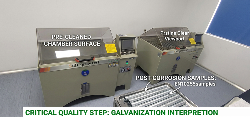
Salt spray testing chambers evaluating hot-dip galvanized coating samples.
Our Quality & Compliance Commitment
In industrial supply chains, balancing procurement budgets with actual installation performance is essential. Every dimensional range, carbon limitation, and coating thickness outlined above is not an optional premium feature; it represents our standard manufacturing baseline.
Our production lines operate strictly under documented quality control systems to ensure that every batch aligns with the necessary technical specifications. We are committed to delivering our steel pipes in strict accordance with the standard, and every single order undergoes rigorous internal verification before final dispatch.
Additionally, YUANTAI DERUN fully welcome and actively cooperate with any independent, third-party inspection organizations appointed by our clients. Reliable quality depends on technical compliance and clear manufacturing transparency.
Post time: Jun-09-2026


